Saturday 10 December 2016

WHAT IS A CHILLER?

WHAT IS A CHILLER IN HVAC SYSTEM?

chiller is a machine that removes heat from a liquid via a vapor-compression or absorption refrigeration cycle. This liquid can then be circulated through a heat exchanger to cool equipment, or another process stream (such as air or process water). As a necessary by product, refrigeration creates waste heat that must be exhausted to ambient or, for greater efficiency, recovered for heating purposes. Concerns in design and selection of chillers include performance, efficiency, maintenance, and product life cycle environmental impact.


In air conditioning systems, chilled water is typically distributed to heat exchangers, or coils, in air handling units or other types of terminal devices which cool the air in their respective space(s). The water is then re-circulated back to the chiller to be cooled again. These cooling coils transfer sensible heat and latent heat from the air to the chilled water, thus cooling and usually dehumidifying the air stream. A typical chiller for air conditioning applications is rated between 15 and 2000 tons, and at least one manufacturer can produce chillers capable of up to 5,200 tons of cooling. Chilled water temperatures can range from 35 to 45 °F (2 to 7 °C), depending upon application requirements. When the chillers for air conditioning systems are not operable or they are in need of repair or replacement, emergency chillers may be used to supply chilled water. Rental chillers are mounted on a trailer so that they can be quickly deployed to the site. Large chilled water hoses are used to connect between rental chillers and air conditioning systems.
In industrial application, chilled water or other liquid from the chiller is pumped through process or laboratory equipment. Industrial chillers are used for controlled cooling of products, mechanisms and factory machinery in a wide range of industries. They are often used in the plastic industries, injection and blow molding, metal working cutting oils, welding equipment, die-casting and machine tooling, chemical processing, pharmaceutical formulation, food and beverage processing, paper and cement processing, vacuum systems, X-ray diffraction, power supplies and power generation stations, analytical equipment, semiconductors, compressed air and gas cooling. They are also used to cool high-heat specialized items such as MRI machines and lasers, and in hospitals, hotels and campuses.
Chillers for industrial applications can be centralized, where a single chiller serves multiple cooling needs, or decentralized where each application or machine has its own chiller. Each approach has its advantages. It is also possible to have a combination of both centralized and decentralized chillers, especially if the cooling requirements are the same for some applications or points of use, but not all.
Decentralized chillers are usually small in size and cooling capacity, usually from 0.2 to 10 short tons (0.179 to 8.929 long tons; 0.181 to 9.072 t). Centralized chillers generally have capacities ranging from ten tons to hundreds or thousands of tons.
Chilled water is used to cool and dehumidify air in mid- to large-size commercial, industrial, and institutional (CII) facilities. Water chillers can be water-cooled, air-cooled, or evaporatively cooled. Water-cooled chillers incorporate the use of cooling towers which improve the chillers' thermodynamic effectiveness as compared to air-cooled chillers. This is due to heat rejection at or near the air's wet-bulb temperature rather than the higher, sometimes much higher, dry-bulb temperature. Evaporatively cooled chillers offer higher efficiencies than air-cooled chillers but lower than water-cooled chillers.
Water-cooled chillers are typically intended for indoor installation and operation, and are cooled by a separate condenser water loop and connected to outdoor cooling towers to expel heat to the atmosphere.
Air-cooled and evaporatively cooled chillers are intended for outdoor installation and operation. Air-cooled machines are directly cooled by ambient air being mechanically circulated directly through the machine's condenser coil to expel heat to the atmosphere. Evaporatively cooled machines are similar, except they implement a mist of water over the condenser coil to aid in condenser cooling, making the machine more efficient than a traditional air-cooled machine. No remote cooling tower is typically required with either of these types of packaged air-cooled or evaporatively cooled chillers.
Where available, cold water readily available in nearby water bodies might be used directly for cooling, place or supplement cooling towers. The Deep Lake Water Cooling System in TorontoCanada, is an example. It uses cold lake water to cool the chillers, which in turn are used to cool city buildings via a district cooling system. The return water is used to warm the city's drinking water supply, which is desirable in this cold climate. Whenever a chiller's heat rejection can be used for a productive purpose, in addition to the cooling function, very high thermal effectiveness is possible.

There are four basic types of compressors used in vapor compression chillers: Reciprocating compression, scroll compression, screw-driven compression, and centrifugalcompression are all mechanical machines that can be powered by electric motors, steam, or gas turbines. They produce their cooling effect via the "reverse-Rankine" cycle, also known as 'vapor-compression'. With evaporative cooling heat rejection, their coefficients-of-performance (COPs) are very high; typically 4.0 or more.
COP 
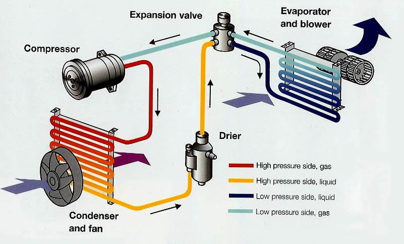
Current vapor-compression chiller technology is based on the "reverse-Rankine" cycle known as vapor-compression. See the attached diagram which outlines the key components of the chiller system.

Diagram showing the components of a water-cooled chiller
Key components of the chiller:
Refrigeration Compressors - are essentially a pump for refrigerant gas. The capacity of the compressor, and hence the chiller cooling capacity is measured in kilowatts input (kW), Horse Power input (HP), or volumetric flow (m3/h, ft3/h). The mechanism for compressing refrigerant gas differs between compressors, and each has its own application. Common refrigeration compressors include Reciprocating, Scroll, Screw, or Centrifugal. These can be powered by electric motors, steam turbines or gas turbines. Compressors can have an integrated motor from a specific manufacturer, or be open drive - allowing the connection to another type of mechanical connection. Compressors can also be either Hermetic (welded closed) or semi-hermetic (bolted together).
In recent years, application of Variable Speed Drive (VSD) technology has increased efficiencies of vapor compression chillers. The first VSD was applied to centrifugal compressor chillers in the late 1970s and has become the norm as the cost of energy has increased. Now, VSDs are being applied to rotary screw and scroll technology compressors.
Condensers can be air-cooled, water-cooled, or evaporative. The condenser is a heat exchanger which allows heat to migrate from the refrigerant gas to either water or air. Air cooled condenser are manufactured from copper tubes (for the refrigerant flow) and aluminium fins (for the air flow). Each condenser has a different material cost and they vary in terms of efficiency. With evaporative cooling condensers, their coefficients-of-performance (COPs) are very high; typically 4.0 or more.
The expansion device or refrigerant metering device (RMD) restricts the flow of the liquid refrigerant causing a pressure drop that vaporizes some of the refrigerant; this vaporization absorbs heat from nearby liquid refrigerant. The RMD is located immediately prior to the evaporator so that the cold gas in the evaporator can absorb heat from the water in the evaporator. There is a sensor for the RMD on the evaporator outlet side which allows the RMD to regulate the refrigerant flow based on the chiller design requirement.
Evaporators can be plate type or shell and tube type. The evaporator is a heat exchanger which allows the heat energy to migrate from the water stream into the refrigerant gas. During the state change of the remaining liquid to gas, the refrigerant can absorb large amounts of heat without changing temperature.

How absorption technology works

The thermodynamic cycle of an absorption chiller is driven by a heat source; this heat is usually delivered to the chiller via steam, hot water, or combustion. Compared to electrically powered chillers, an absorption chiller has very low electrical power requirements - very rarely above 15 kW combined consumption for both the solution pump and the refrigerant pump. However, its heat input requirements are large, and its COP is often 0.5 (single-effect) to 1.0 (double-effect). For the same tonnage capacity, an absorption chiller requires a much larger cooling tower than a vapor-compression chiller. However, absorption chillers, from an energy-efficiency point of view, excel where cheap, high-grade heat or waste heat is readily available. In extremely sunny climates, solar energy has been used to operate absorption chillers.
The single-effect absorption cycle uses water as the refrigerant and lithium bromide as the absorbent. It is the strong affinity that these two substances have for one another that makes the cycle work. The entire process occurs in almost a complete vacuum.
  1. Solution Pump : A dilute lithium bromide solution (63% concentration) is collected in the bottom of the absorber shell. From here, a hermetic solution pump moves the solution through a shell and tube heat exchanger for preheating.
  2. Generator : After exiting the heat exchanger, the dilute solution moves into the upper shell. The solution surrounds a bundle of tubes which carries either steam or hot water. The steam or hot water transfers heat into the pool of dilute lithium bromide solution. The solution boils, sending refrigerant vapor upward into the condenser and leaving behind concentrated lithium bromide. The concentrated lithium bromide solution moves down to the heat exchanger, where it is cooled by the weak solution being pumped up to the generator.
  3. Condenser : The refrigerant vapor migrates through mist eliminators to the condenser tube bundle. The refrigerant vapor condenses on the tubes. The heat is removed by the cooling water which moves through the inside of the tubes. As the refrigerant condenses, it collects in a trough at the bottom of the condenser.
  4. Evaporator : The refrigerant liquid moves from the condenser in the upper shell down to the evaporator in the lower shell and is sprayed over the evaporator tube bundle. Due to the extreme vacuum of the lower shell [6 mm Hg (0.8 kPa) absolute pressure], the refrigerant liquid boils at approximately 39 °F (4 °C), creating the refrigerant effect. (This vacuum is created by hygroscopic action - the strong affinity lithium bromide has for water - in the Absorber directly below.)
  5. Absorber : As the refrigerant vapor migrates to the absorber from the evaporator, the strong lithium bromide solution from the generator is sprayed over the top of the absorber tube bundle. The strong lithium bromide solution actually pulls the refrigerant vapor into solution, creating the extreme vacuum in the evaporator. The absorption of the refrigerant vapor into the lithium bromide solution also generates heat which is removed by the cooling water. Now the dilute lithium bromide solution collects in the bottom of the lower shell, where it flows down to the solution pump. The chilling cycle is now completed and the process begins once again.[5]
Industrial chillers typically come as complete, packaged, closed-loop systems, including the chiller unit, condenser, and pump station with recirculating pump, expansion valve, no-flow shutdown, internal cold water control. The internal tank helps maintain cold water temperature and prevents temperature spikes from occurring. Closed-loop industrial chillers recirculate a clean coolant or clean water with condition additives at a constant temperature and pressure to increase the stability and reproducibility of water-cooled machines and instruments. The water flows from the chiller to the application's point of use and back.
If the water temperature differentials between inlet and outlet are high, then a large external water tank would be used to store the cold water. In this case the chilled water is not going directly from the chiller to the application, but goes to the external water tank which acts as a sort of "temperature buffer." The cold water tank is much larger than the internal water goes from the external tank to the application and the return hot water from the application goes back to the external tank, not to the chiller.
The less common open loop industrial chillers control the temperature of a liquid in an open tank or sump by constantly recirculating it. The liquid is drawn from the tank, pumped through the chiller and back to the tank. In industrial water chillers is the use of water cooling instead of air cooling. In this case the condenser does not cool the hot refrigerant with ambient air, but uses water that is cooled by a cooling tower. This development allows a reduction in energy requirements by more than 15% and also allows a significant reduction in the size of the chiller, due to the small surface area of the water-based condenser and the absence of fans. Additionally, the absence of fans allows for significantly reduced noise levels.
Most industrial chillers use refrigeration as the media for cooling, but some rely on simpler techniques such as air or water flowing over coils containing the coolant to regulate temperature. Water is the most commonly used coolant within process chillers, although coolant mixtures (mostly water with a coolant additive to enhance heat dissipation) are frequently employed.

Important specifications to consider when searching for industrial chillers include the total life cycle cost, the power source, chiller IP rating, chiller cooling capacity, evaporator capacity, evaporator material, evaporator type, condenser material, condenser capacity, ambient temperature, motor fan type, noise level, internal piping materials, number of compressors, type of compressor, number of fridge circuits, coolant requirements, fluid discharge temperature, and COP (the ratio between the cooling capacity in RT to the energy consumed by the whole chiller in KW). For medium to large chillers this should range from 3.5 to 7.0, with higher values meaning higher efficiency. Chiller efficiency is often specified in kilowatts per refrigeration ton (kW/RT).
Process pump specifications that are important to consider include the process flow, process pressure, pump material, elastomer and mechanical shaft seal material, motor voltage, motor electrical class, motor IP rating and pump rating. If the cold water temperature is lower than −5 °C, then a special pump needs to be used to be able to pump the high concentrations of ethylene glycol. Other important specifications include the internal water tank size and materials and full load current.
Control panel features that should be considered when selecting between industrial chillers include the local control panel, remote control panel, fault indicators, temperature indicators, and pressure indicators.
Additional features include emergency alarms, hot gas bypass, city water switchover, and casters.
Demountable chillers are also an option for deployment in remote areas and where the conditions may be hot and dusty.
A vapor-compression chiller uses a refrigerant internally as its working fluid. Many refrigerants options are available; when selecting a chiller, the application cooling temperature requirements and refrigerant's cooling characteristics need to be matched. Important parameters to consider are the operating temperatures and pressures.
There are several environmental factors that concern refrigerants, and also affect the future availability for chiller applications. This is a key consideration in intermittent applications where a large chiller may last for 25 years or more. Ozone depletion potential (ODP) and global warming potential (GWP) of the refrigerant need to be considered. ODP and GWP data for some of the more common vapor-compression refrigerants (noting that many of these refrigerants are highly flammable and/or toxic):
RefrigerantODPGWP
R1212400
R1230.01276
R134a01300
R220.051700
R290 (propane)03
R401a0.027970
R404a03260
R407a02000
R407c01525
R408a0.0163020
R409a0.0391290
R410a01725
R5000.7 ???
R5020.185600
R50703300
R600a03
R744 (CO2)01
R717 (ammonia)00
R718 (water)00
R12 is the ODP reference. CO2 is the GWP reference
The refrigerants used in the chillers sold in Europe are mainly R410a (70%), R407c (20%) and R134a (10%).

Wednesday 1 June 2016

What are Deluge Valves?

iitcenter.blogspot.in

What are Deluge Valves?

http://mepsite.blogspot.in/
Deluge Valves are used in conditions that call for quick application of large volumes of water and, for that reason, are often integral components in fire protection systems. In this article, PIF explain how deluge valves work, what their advantages and disadvantages are, and where you can lay your hands on one. - http://mepsite.blogspot.in/


Deluge systems deliveriitcenter.blogspot.in large quantities of water, over a large area, in a relatively short period of time. They are commonly used in fixed fire protection systems whose pipe system is empty until the deluge valve distributes pressurized water from open nozzles or sprinklers.

Deluge systems contain more components and equipment than wet pipe and dry systems. So for that matter they are more complex. Detection systems can include heat, smoke, ultraviolet (UV), or infrared (IR).
http://mepsite.blogspot.in/

Applications for Deluge Valves:


Deluge systems are used in conditions that require quick application of large volumes of water. They create a ‘buffer zone’ in hazardous areas or in areas where fires can spread rapidly. They can also be used to cool surfaces to prevent deformation or structural collapse. Or to protect tanks, transformers, or process lines from explosion.


Other examples include: tanks containing combustible solutions; equipment pits; storage or process areas containing substances with a low flash point; or product handling systems.
http://mepsite.blogspot.in/

Advantages and disadvantages of Deluge Valves:

Advantages:

  1. Less expensive than other methods,
  2. Uses water for extinguishing.

Disadvantages:

  1. Can damage sensitive or electronic equipment,
  2. Longer clean-up time than powder and gas systems,http://mepsite.blogspot.in/
  3. Requires a large water reservoir to operate.

Monday 16 May 2016

Types of Fire Sprinkler Systems


4 Types of Fire Sprinkler Systems

It is best to have protection in commercial buildings in case of fire or smoke. Installing a sprinkler system is a good preventative measure to take. There are various types of fire sprinklers and below are descriptions of these so you know which one is best suited for your commercial building.


Pre-action:

Pre-action fire sprinkler systems are filled with air and water is allowed to pass through when the smoke alarm or detector goes off. This type of system requires two triggers to start water flow. It helps greatly that the pre-action fire sprinkler can be set to prevent water from spouting in case of a false alarm or a mechanical failure. The pre-action system is good for use in places where the sprinklers are only necessary when there is an actual fire so other items in the building do not get water damage from an accidental sprinkling. Such buildings include libraries and data centers. These places contain items of high value like electronics and goods damageable by water such as books

Dry Pipe:

Dry pipe sprinklers are similar to pre-action systems as they use pressurized air in the pipe which exits before water escapes. This causes a minute delay in water discharge but is ideal for buildings with low temperatures so the pipes do not freeze. These fire sprinkler systems have a fast opening tool to get rid of the air and speed up the flow of water. Warehouses located in the north are a good example of what buildings should use dry pipe sprinklers.
www.mepsite.blogspot.in

Wet Pipe:

Wet pipe fire sprinklers constantly have water in them. This allows for a quick reaction to a fire and is the most common type of sprinkler installed in buildings. A type of building that uses the wet pipe system is a high-rise or office building with a few floors. This fire sprinkler system is cost efficient and low maintenance.
www.mepsite.blogspot.in

Deluge:

These types of fire sprinkler systems also need a smoke or heat detector like the pre-action system. A deluge system has open nozzles that can be used when a hazard is present. When flammable liquids are spread across a floor, deluge fire sprinklers are good to have. In that case, buildings such as industrial parks and buildings with many tanks have deluge fire sprinkler systems installed.

Thursday 7 April 2016

Pressure Testing for Chilled Water Piping

Pressure Testing for Chilled Water Piping

1. Purpose:

The purpose of this method is to make sure that the pressure testing of chilled water piping system is done safely as per client requirement and applicable standars.

2. Scope of Work: 


  • This Method Statement covers the hydro static pressure testing of chilled water piping (CHW) pipework at the project and to be followed for all piping works at sites.
  • Prior to start of the hydro static pressure testing all other works on the system shall have been snagged by construction team and de-snagged and signed off by the quality department.
  • This method statement is for chilled water system black mild steel piping and fittings.

3. Responsibilities:

Construction Manager,
Mechanical Engineer,
Foreman,
Superintendent,
QA/QC Engineer.


4. Pressure Testing Method of Statement:

  1. Permit to work for pressure test to be obtained from safety department.
  2. All open flanged, valved or screwed ends will be blanked off.
  3. The fill point will be installed at the lowest point of the system and a valve vent at the highest point of the system to be tested. The vent will be piped to a drain point.
  4. Pressure Gauges with valid Calibration Certificates/Stickers will be fitted adjacent to the pressure pump.
  5. Pipe work will be water sufficiently in advance of the test to allow it to come to room temperature so that any sweating can evaporate. When the systems sufficiently filled the vent valve will be opened and allowed to run freely for a period of 5 minutes to ensure all the air is out of the system, at that point the valve will be closed.
  6. When the system is full and vented the test rig will be linked to the system and the pressure increased to the required system test pressure, as required by the specification 1.5 the operating pressure. when the test pressure is reached the valve at the fill point will be closed for a period of 15 minutes to stabilize the system, the gauges will be checked to see any pressure has loss due to stabilization, if so the test rig will be applied to bring the system test pressure back up to the specification requirements. Upon re-pressurization the test rig shall then be dismantled for the system.
  7. Care will be taken at this point to record the ambient room temperature of the start and finish time of the test. The duration of the test will be 24 hours and temperatures will be recorded frequently.
  8. A visual inspection of joints will take place during the test period to check the leaks, if any leakage found the test will be aborted. After the leakage is rectified, the above procedure will be repeated for a re-test to take place.
  9. On satisfactory completion of test, witnessed by the client, the pressure will be released through the vent pipe. The system then shall be drained. Pressure testing report shall be prepared and signed by the client or any other concerned party.

5. Health and Safety Requirements:


  1. Spot Safety meeting will be done by competent engineer to the working group.
  2. Fitting, thread and connections will be checking up for broken or un-threaded parts.
  3. To make sure every one in testing area knows that the pressure test will be done and proper tags to be displayed.
  4. Ensure that all pipes are fasted properly.
  5. Warnings signs will to be displayed  in both English and local language.
  6. Valves operations to be understood by operator before pressure test starts.
  7. Restrict the access for common people to testing area, use communication system for announcements, etc.
  8. Only authorized persons are allowed to check the pipes during the pressure in progress.
  9. After the test is complete, the pressure should be released slowly and open all valves once the pressure is zero, to ensure that there is no pressure trapped anywhere in the system.


Monday 4 April 2016

Air Conditioner Working Principle.


Window air conditioners are very simple appliances. They operate on the exact same principles as a refrigerator, freezer, or dehumidifier.

Please look for information on how window air conditioners work in these areas:

Cooling:

All residential window air conditioners have a cooling system made up of four primary components, a compressor, an evaporator, a metering device, and a condenser. Air conditioner cooling systems are better understood if you think of them as devices that remove warmth from the air rather than cooling the air.

Blower fan:

When the unit is running, the circulating fan and compressor are running simultaneously. The fan motor has two fan blades attached to it on either end. The fan blade on the inside part of the unit continually draws room air over the evaporator coils, which are cold. The fan blade on the outside part of the unit continually draws fresh outside air over the condenser coils, which are warm. Because the evaporator coils are cold, they cause moisture in the room to collect on them, much like a cup of ice water on a warm, humid day. When the amount of moisture increases, it begins to drip down off of the coils into the bottom pan of the air conditioner.

Thermostat control:

The thermostat on a window air conditioner works by sensing the air temperature entering the air conditioner. As the air entering the unit reaches the set temperature it will cause the compressor to turn off. The blower may continue to run depending on the selection chosen on the control panel. Digital thermostats work on a similar principle but display a more precise temperature.
www.facebook.com

Selector switches:

The air conditioner selector switches allow the user to choose the fan speed. The compressor always runs at the same speed regardless of the settings. If low cool is chosen, for example, the fan runs at a slower speed but the compressor still offers the same cooling capacity. There are other switches to control louver operation and other features on some units.

Air conditioning Systems

Selection criteria for air conditioning systems: 

Selection of a suitable air conditioning system depends on: 
1. Capacity, performance and spatial requirements 
2. Initial and running costs 
3. Required system reliability and flexibility 
4. Maintainability 
5. Architectural constraints Q plant Thermal Distribution System 

The relative importance of the above factors varies from building owner to owner and may vary from project to project. 
The typical space requirement for large air conditioning systems may vary from about 4 percent to about 9 percent of the gross building area, depending upon the type of the system. 
Normally based on the selection criteria, the choice is narrowed down to 2 to 3 systems, out of which one will be selected finally.
http://mepsite.blogspot.in/


Classification of air conditioning systems: 

Based on the fluid media used in the thermal distribution system, air conditioning systems can be classified as: 
1. All air systems 
2. All water systems 
3. Air- water systems 
4. Unitary refrigerant based systems.

All air systems: 

As the name implies, in an all air system air is used as the media that transports energy from the conditioned space to the A/C plant. In these systems air is processed in the A/C plant and this processed air is then conveyed to the conditioned space through insulated ducts using blowers and fans. This air extracts (or supplies in case of winter) the required amount of sensible and latent heat from the conditioned space. The return air from the conditioned space is conveyed back to the plant, where it again undergoes the required processing thus completing the cycle. No additional processing of air is required in the conditioned space. All air systems can be further classified into: 
1. Single duct systems, or 
2. Dual duct systems 
The single duct systems can provide either cooling or heating using the same duct, but not both heating and cooling simultaneously. These systems can be further classified into: 
1. Constant volume, single zone systems 
2. Constant volume, multiple zone systems 
3. Variable volume systems 
4 The dual duct systems can provide both cooling and heating simultaneously.
https://www.facebook.com/mepsite/

These systems can be further classified into: 

1. Dual duct, constant volume systems 
2. Dual duct variable volume systems 

Advantages of Variable Speed

Advantages of Variable Speed: 

Variable-speed blower motors are designed to provide greater comfort through reduced initial air velocities and noise. When the unit first turns on, the blower operates at low speed, which not only provides less noise than a single-speed blower, but also allows the compressor and coil to ramp up before the unit begins moving large volumes of air through the system.
Most motors are designed to operate at a constant speed and provide a constant output. While in many cases this may be more than adequate, it is not in all. Two-speed induction motors can improve efficiency for refrigerators, air conditioners, and blowers.

Although in theory this can be done with any induction motor application, a greater value is obtained with appliances that run frequently. With a two-speed mode of operation, long time periods that would normally use full power can be replaced by long periods of substantially less power with short periods when full power may be needed.

Currently, residential central air conditioners, blowers (furnaces), and clothes washers take advantage of this technology since small changes in speed can drastically cut down on power usage (power consumption is approximately proportional to the cube root of shaft speed, e.g., a shaft reduction of 10% corresponds to at 27% reduction of power).

Monday 21 March 2016

what is FCU, AHU AND FAHU?

FCU:

FCU is the abbreviation used for FAN COIL UNIT that are available for either DX or chilled water system that houses refrigerant or chilled water coil respectively. Beside the type of coil used, the other components are common such as the blower fan & filters. FCUs are usually available from 0.75 to 5 TR from various brands across the globe.


Fan Coil Unit, as the name suggests the unit houses the Blower(Fan), the evaporator Coil (for DX System) / Heat Exchanger Coil( for sytems other than DX), Filter and sometimes Heater Coil(Electric). Usually takes the hot air from room and cool it then suply to room.
FCU is fan coil unit which is intalled for samll capacities and have less options than AHU like no humidity control and no special options for heat recovery of air filters.
Fan Coil Unit, as the name suggests the unit houses the Blower(Fan), the evaporator Coil (for DX System) / Heat Exchanger Coil( for sytems other than DX), Filter and sometimes Heater Coil(Electric). Usually employed for upto 4 to 5tons , some manufacturers do make higher capacities but will be belt driven which could be noisy.

AHU:

AHU is generally a bigger system than FCU. AHU is more complex than the FCU and that AHU are often used in bigger establishments or spaces. The AHU system usually channels air through ducts whereas the FCU may have or don't have any ductworks. AHU system treats outside air while FCUs basically recycle or re-circulates the air. AHU have sections for reheating and humidifying whereas the FCU may have heaters but no Humdification. FCU are often observed to be noisier than the AHU.


AHU is the abbreviation used for AIR HANDLING UNIT; is an advance type of FCU beyond 5 TR capacity. They are either available in standard sizes or custom size & body construction. In addition to the standard components (blower fan & filter), it has advance filters, UV light, mixing chambers, etc. depending upon the requirement & construction.
AHU is the abbreviation used for AIR HANDLING UNIT; is an advance type of FCU and 
normally made as to customer demand-such as heater,uv lamps,carbon filter, hepa filter, pre filter and bag filters are normally using in all AHU'S with return air duct + some fresh air also and suply the cool purified air to the premises by using blower and motor running  with or without VFD.
AHU means Air Handling Units and are available in number of varities and tonnages from small upto large capacities. Thay are available with number of modifications which are normlly not available in FCUs as mentioned above.
Air Handling Unit, think of AHU as a bigger FCU. AHU typically houses Blower, Heating or Cooling Coil(or both) and Filters. AHU's can be given provision for adding Fresh Air(Outside Air) , Humidifier and UV lights (Seen a demonstation conducted by carrier and their studies shows no or very very less amount of mould forming at the coils and ofcourse bacteria and viruses) for killing organic substances. AHU's are be available for larger tonnages too.
FCU is an indoor unit with small tonage capacities used with central air conditioning systems such as chillers system.
AHU is an indoor and also can be used as outdoor also used with central air conditioning systems such as chillers system but have a wide range of capacities having  a great static pressure of fans to deliver the air through air ducts to big cooling zone areas.

FAHU:

FAHU is the abbreviation used for FRESH AIR HANDLING UNIT. These are usually centralized units employed to induce fresh air quantities to the confines spaces. They come into picture wherever there are limitations to fresh air intake either directly or through AHUs. FAHUs are either of normal construction having 100% fresh air through a blower fan or Treated FAHU that employs an additional cooling coil to induce treated air into the confined space without deteriorating the indoor conditions. It all depends upon the selection of the designer to provide an optimum HVAC solution.


Fresh Air Handling Unit, same as a AHU but dosent have air recirculation option(100% Fresh Air is used). The Return air is extracted to the atmosphere either used Heat Wheel or coils like heat exchanger coil,pre cooling coil and cooling coil with pre filter, bag filter,UV lamp,HEPA filter,Carbon filter { where it is applicable }and for some units using Electronic filter also.Then suply the purified cool air to the rooms with belt driven motor or direct drive controlled by VFD.
When the AHU is used for fresh air only then it is known as FAHU (Fresh Air Handling Unit). means there is no return duct only fresh air supply to the area.
Fresh Air Handling Unit, same as a AHU but dosent have air recirculation option(100% Fresh Air is used). The Return air is extracted to the atmosphere, usually used in places like hospitals where contaminated return air is not advised to be reused. The extract air is most likely to be of at a lower temperature that the fresh air taken by the FAHU, so inorder to increase the efficiency of the system a heat exchanger(usually Heat wheel or Cross flow Plate type HX) is used where the temperature of fresh air is transfered to the extract air.
FAHU is same like AHU with fresh air100%.

Saturday 19 March 2016

Dampers

Control Dampers:

For controlling air distribution, such as

Fire damper:

A thermally actuated damper arranged to automatically restrict the passage of fire and/or heat at a point where an opening violates the integrity of a fire partition or floor.

Smoke damper: 

A damper arranged to control passage of smoke through an opening or a duct.

Volume control damper (VCD): 

A device used to regulate the flow of air in an HVAC system.


Common types: Š 

  • Opposed blade dampers (e.g. in AHU).
  • Parallel blade dampers.
  • Butterfly dampers (e.g. in VAV box).
  • Linear air valves (e.g. in fume hood).
  • Specialty dampers.

Damper Sizing


  • Typically chosen based on duct size and convenience of location.
  • Proper selection and sizing provides the following benefits: Š 
  1. Lower installation cost (damper sizes are smaller).
  2. Smaller actuators or a fewer number of them are required.
  3. Reduced energy costs (smaller damper, less overall leakage).
  4. Improved control characteristics (rangeability) because the ratio of total damper flow to minimum controllable flow is increased.
  5. Improved operating characteristics (linearity).

Selecting and Sizing Dampers:


The three basic damper applications are: „ 
  • Two-position duty.
  • Capacity control duty.
  • Mixing duty.

2 way and 3 way valves


2-Way and 3-Way Valves

2-way valves are pretty simple and straight-forward. A 2-way valve is any type of valve with two ports: an inlet and an outlet port, typically labeled “A” and “AB” respectively. 2-way valves are used in many applications, from basic on/off to more complex variable flow applications with pumps and VFDs. The type of valve you need for an application depends on the amount of flow, the degree of control, shut-off, and pressure drops over the valve.


 Fig: 2 way valve

Fig: 3 way valve connections


3-way valves have, yes, three ports, labeled “A”, “B”, and “AB”. Port “AB” is common to the “A” or “B” port. 3-way valves are commonly found in constant flow/volume pumping systems and can be either mixing or diverting valves. 3-way valves can be piped in the supply or return. If in the supply, then a diverting valve is used. If piped in the return, a mixing valve is used. Ball valves can be piped to be mixing or diverting, but globe valves require different bodies for mixing or diverting. 


Mixing applications have the 3-way valve configured with two inputs from the supply piping and one output to the return piping, thus mixing together two inputs before sending it out. Mixing valves are most commonly used with modulating control but can be on/off.

Diverting applications have the 3-way valve configured with one input from the supply side and two outputs to the return piping. In general, diverting valves are more expensive than mixing valves.


2 Way Valve:

2 Way (Or 2 Ports) Valve is passing the water in one direction only. so if the valve is fully close it will trap the water before it. this will lead to a pressure increase in this branch

3 Way Valve:

3 Way (Or 3 ports) Valve is passing the water in two directions.
so if the valve is fully open the full amount of water will be moving in one direction, if it closed the water will pass to the other direction, if the valve is partially open then percent of the water will flow through direction 1 and the remaining will pass through the other (for Diverting Valve which installed in the supply line).

In another cases if we install the valve in the return line so if the valve is open water will flow through the unit (Cooling coil as example) then pass through main direction. if the valve is close the water will by pass the unit and then flow through the other direction through the valve (Mixing Valve which installed in the Return line).

This will not cause the pressure rising. Why we use the 2 way valve? when you use the 2 way valves in HVAC system in all the equipment's in your building this means that you will not need all the chilled water to go through your system all the time if you don't need much cooling. so you will be able to reduce the speed of the secondary pumps of your system. this will lead to a huge energy saving in the running cost of your building (depend on the number of Pumps and their sizes). Also you will be able to reduce the size of your pumps. But in this case you have to use Variable Speed Pumps. Also you should have 2 sets of Pumps, One set constant with Speed for Chillers and another set to serve the building. ans also By Pass Valve to guarantee the min flow of the chillers. Otherwise you can use one set with a variable flow chillers. This has to be a decision in the mechanical design stage depend on the cost calculation of the project.

Advantages of 2-Way Valves:

  •  „Less expensive to buy and install.
  • Result in variable flow which reduces pumping energy.
  • Reduced piping heat losses and pump energy.
  • Potentially lower costs for pumping and distribution systems.
  • System balancing is reduced or eliminated.

Disadvantages of 2-Way Valves:

  • Most chillers and some boilers cannot handle widely varying flow rates.
  • Differential pressures will increase across control valves, reducing system controllability.

Control Valve Ratings

  • Flow coefficient.
  • Close-off rating: Š The maximum pressure drop that a valve can withstand without leakage while in the full closed position.
  • Pressure drop: Š The difference in upstream and downstream pressures of the fluid flowing through the valve.
  • Maximum pressure and temperature: Š The maximum pressure and temperature limitations of fluid flow that a valve can withstand.

Location of Control Valves:

  • „ At the outlet on the top of cooling/heating coils.
  1. Avoid coil starvation from water flow (lower pressure)Š
  2. Flow of water from the bottom to the top (avoid air bubble).
  • Flow measuring & balancing device should be placed after the control valve.
  • Provide a means of shut-off to allow a proper means for servicing.

Conclusion:

1. use the 2 way Valve in the system that can withstand the variable water flow
2. use the 3 way valve in the systems that needs a constant water flow.


Selecting & Sizing Valves:

Control valve selection depends on: „ 
  • The fluid being controlled.
  • Valve style: 2-way or 3-way.
  • Control mode: modulating or 2-position.
  • Maximum fluid temperature.
  • Maximum inlet pressure.
  • Desired flow characteristic.
  • Maximum fluid flow rate.
  • Desired pressure drop when valve is full open.
  • Turn-down ratio.
  • Close-off pressure.

Flow Characteristic Selection: 

The desired flow characteristic is a function of: „ 
  • The heat transfer device being controlled and its flow versus capacity characteristic.
  • The control of fluid supply temperature.
  • The control of the differential pressure across the valve.


About

HVAC is the technology of indoor and vehicular environmental comfort. Its goal is to provide thermal comfort and acceptable indoor air quality. HVAC system design is a subdiscipline of mechanical engineering, based on the principles of thermodynamics, fluid mechanics, and heat transfer. Refrigeration is sometimes added to the field's abbreviation as HVAC&R or HVACR, (heating,ventilating and air-conditioning & Refrigeration) or ventilating is dropped as in HACR (such as the designation of HACR-rated circuit breakers). HVAC is important in the design of medium to large industrial and office buildings such as skyscrapers, onboard vessels, and in marine environments such as aquariums, where safe and healthy building conditions are regulated with respect to temperature and humidity, using fresh air from outdoors. Ventilating or ventilation (the V in HVAC) is the process of "exchanging" or replacing air in any space to provide high indoor air quality which involves temperature control, oxygen replenishment, and removal of moisture, odors, smoke, heat, dust, airborne bacteria, and carbon dioxide. Ventilation removes unpleasant smells and excessive moisture, introduces outside air, keeps interior building air circulating, and prevents stagnation of the interior air. Ventilation includes both the exchange of air to the outside as well as circulation of air within the building. It is one of the most important factors for maintaining acceptable indoor air quality in buildings. Methods for ventilating a building may be divided into mechanical/forced and natural types.