Showing posts with label HVAC. Show all posts

Thursday, 7 April 2016

Pressure Testing for Chilled Water Piping

Pressure Testing for Chilled Water Piping

1. Purpose:

The purpose of this method is to make sure that the pressure testing of chilled water piping system is done safely as per client requirement and applicable standars.

2. Scope of Work: 


  • This Method Statement covers the hydro static pressure testing of chilled water piping (CHW) pipework at the project and to be followed for all piping works at sites.
  • Prior to start of the hydro static pressure testing all other works on the system shall have been snagged by construction team and de-snagged and signed off by the quality department.
  • This method statement is for chilled water system black mild steel piping and fittings.

3. Responsibilities:

Construction Manager,
Mechanical Engineer,
Foreman,
Superintendent,
QA/QC Engineer.


4. Pressure Testing Method of Statement:

  1. Permit to work for pressure test to be obtained from safety department.
  2. All open flanged, valved or screwed ends will be blanked off.
  3. The fill point will be installed at the lowest point of the system and a valve vent at the highest point of the system to be tested. The vent will be piped to a drain point.
  4. Pressure Gauges with valid Calibration Certificates/Stickers will be fitted adjacent to the pressure pump.
  5. Pipe work will be water sufficiently in advance of the test to allow it to come to room temperature so that any sweating can evaporate. When the systems sufficiently filled the vent valve will be opened and allowed to run freely for a period of 5 minutes to ensure all the air is out of the system, at that point the valve will be closed.
  6. When the system is full and vented the test rig will be linked to the system and the pressure increased to the required system test pressure, as required by the specification 1.5 the operating pressure. when the test pressure is reached the valve at the fill point will be closed for a period of 15 minutes to stabilize the system, the gauges will be checked to see any pressure has loss due to stabilization, if so the test rig will be applied to bring the system test pressure back up to the specification requirements. Upon re-pressurization the test rig shall then be dismantled for the system.
  7. Care will be taken at this point to record the ambient room temperature of the start and finish time of the test. The duration of the test will be 24 hours and temperatures will be recorded frequently.
  8. A visual inspection of joints will take place during the test period to check the leaks, if any leakage found the test will be aborted. After the leakage is rectified, the above procedure will be repeated for a re-test to take place.
  9. On satisfactory completion of test, witnessed by the client, the pressure will be released through the vent pipe. The system then shall be drained. Pressure testing report shall be prepared and signed by the client or any other concerned party.

5. Health and Safety Requirements:


  1. Spot Safety meeting will be done by competent engineer to the working group.
  2. Fitting, thread and connections will be checking up for broken or un-threaded parts.
  3. To make sure every one in testing area knows that the pressure test will be done and proper tags to be displayed.
  4. Ensure that all pipes are fasted properly.
  5. Warnings signs will to be displayed  in both English and local language.
  6. Valves operations to be understood by operator before pressure test starts.
  7. Restrict the access for common people to testing area, use communication system for announcements, etc.
  8. Only authorized persons are allowed to check the pipes during the pressure in progress.
  9. After the test is complete, the pressure should be released slowly and open all valves once the pressure is zero, to ensure that there is no pressure trapped anywhere in the system.


Monday, 4 April 2016

Air Conditioner Working Principle.


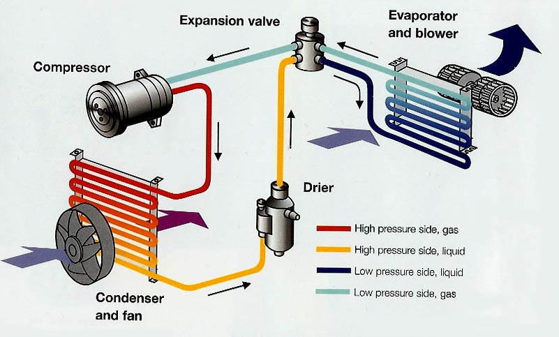
Window air conditioners are very simple appliances. They operate on the exact same principles as a refrigerator, freezer, or dehumidifier.

Please look for information on how window air conditioners work in these areas:

Cooling:

All residential window air conditioners have a cooling system made up of four primary components, a compressor, an evaporator, a metering device, and a condenser. Air conditioner cooling systems are better understood if you think of them as devices that remove warmth from the air rather than cooling the air.

Blower fan:

When the unit is running, the circulating fan and compressor are running simultaneously. The fan motor has two fan blades attached to it on either end. The fan blade on the inside part of the unit continually draws room air over the evaporator coils, which are cold. The fan blade on the outside part of the unit continually draws fresh outside air over the condenser coils, which are warm. Because the evaporator coils are cold, they cause moisture in the room to collect on them, much like a cup of ice water on a warm, humid day. When the amount of moisture increases, it begins to drip down off of the coils into the bottom pan of the air conditioner.

Thermostat control:

The thermostat on a window air conditioner works by sensing the air temperature entering the air conditioner. As the air entering the unit reaches the set temperature it will cause the compressor to turn off. The blower may continue to run depending on the selection chosen on the control panel. Digital thermostats work on a similar principle but display a more precise temperature.
www.facebook.com

Selector switches:

The air conditioner selector switches allow the user to choose the fan speed. The compressor always runs at the same speed regardless of the settings. If low cool is chosen, for example, the fan runs at a slower speed but the compressor still offers the same cooling capacity. There are other switches to control louver operation and other features on some units.

Advantages of Variable Speed

Advantages of Variable Speed: 

Variable-speed blower motors are designed to provide greater comfort through reduced initial air velocities and noise. When the unit first turns on, the blower operates at low speed, which not only provides less noise than a single-speed blower, but also allows the compressor and coil to ramp up before the unit begins moving large volumes of air through the system.
Most motors are designed to operate at a constant speed and provide a constant output. While in many cases this may be more than adequate, it is not in all. Two-speed induction motors can improve efficiency for refrigerators, air conditioners, and blowers.

Although in theory this can be done with any induction motor application, a greater value is obtained with appliances that run frequently. With a two-speed mode of operation, long time periods that would normally use full power can be replaced by long periods of substantially less power with short periods when full power may be needed.

Currently, residential central air conditioners, blowers (furnaces), and clothes washers take advantage of this technology since small changes in speed can drastically cut down on power usage (power consumption is approximately proportional to the cube root of shaft speed, e.g., a shaft reduction of 10% corresponds to at 27% reduction of power).

Monday, 21 March 2016

what is FCU, AHU AND FAHU?

FCU:

FCU is the abbreviation used for FAN COIL UNIT that are available for either DX or chilled water system that houses refrigerant or chilled water coil respectively. Beside the type of coil used, the other components are common such as the blower fan & filters. FCUs are usually available from 0.75 to 5 TR from various brands across the globe.


Fan Coil Unit, as the name suggests the unit houses the Blower(Fan), the evaporator Coil (for DX System) / Heat Exchanger Coil( for sytems other than DX), Filter and sometimes Heater Coil(Electric). Usually takes the hot air from room and cool it then suply to room.
FCU is fan coil unit which is intalled for samll capacities and have less options than AHU like no humidity control and no special options for heat recovery of air filters.
Fan Coil Unit, as the name suggests the unit houses the Blower(Fan), the evaporator Coil (for DX System) / Heat Exchanger Coil( for sytems other than DX), Filter and sometimes Heater Coil(Electric). Usually employed for upto 4 to 5tons , some manufacturers do make higher capacities but will be belt driven which could be noisy.

AHU:

AHU is generally a bigger system than FCU. AHU is more complex than the FCU and that AHU are often used in bigger establishments or spaces. The AHU system usually channels air through ducts whereas the FCU may have or don't have any ductworks. AHU system treats outside air while FCUs basically recycle or re-circulates the air. AHU have sections for reheating and humidifying whereas the FCU may have heaters but no Humdification. FCU are often observed to be noisier than the AHU.


AHU is the abbreviation used for AIR HANDLING UNIT; is an advance type of FCU beyond 5 TR capacity. They are either available in standard sizes or custom size & body construction. In addition to the standard components (blower fan & filter), it has advance filters, UV light, mixing chambers, etc. depending upon the requirement & construction.
AHU is the abbreviation used for AIR HANDLING UNIT; is an advance type of FCU and 
normally made as to customer demand-such as heater,uv lamps,carbon filter, hepa filter, pre filter and bag filters are normally using in all AHU'S with return air duct + some fresh air also and suply the cool purified air to the premises by using blower and motor running  with or without VFD.
AHU means Air Handling Units and are available in number of varities and tonnages from small upto large capacities. Thay are available with number of modifications which are normlly not available in FCUs as mentioned above.
Air Handling Unit, think of AHU as a bigger FCU. AHU typically houses Blower, Heating or Cooling Coil(or both) and Filters. AHU's can be given provision for adding Fresh Air(Outside Air) , Humidifier and UV lights (Seen a demonstation conducted by carrier and their studies shows no or very very less amount of mould forming at the coils and ofcourse bacteria and viruses) for killing organic substances. AHU's are be available for larger tonnages too.
FCU is an indoor unit with small tonage capacities used with central air conditioning systems such as chillers system.
AHU is an indoor and also can be used as outdoor also used with central air conditioning systems such as chillers system but have a wide range of capacities having  a great static pressure of fans to deliver the air through air ducts to big cooling zone areas.

FAHU:

FAHU is the abbreviation used for FRESH AIR HANDLING UNIT. These are usually centralized units employed to induce fresh air quantities to the confines spaces. They come into picture wherever there are limitations to fresh air intake either directly or through AHUs. FAHUs are either of normal construction having 100% fresh air through a blower fan or Treated FAHU that employs an additional cooling coil to induce treated air into the confined space without deteriorating the indoor conditions. It all depends upon the selection of the designer to provide an optimum HVAC solution.


Fresh Air Handling Unit, same as a AHU but dosent have air recirculation option(100% Fresh Air is used). The Return air is extracted to the atmosphere either used Heat Wheel or coils like heat exchanger coil,pre cooling coil and cooling coil with pre filter, bag filter,UV lamp,HEPA filter,Carbon filter { where it is applicable }and for some units using Electronic filter also.Then suply the purified cool air to the rooms with belt driven motor or direct drive controlled by VFD.
When the AHU is used for fresh air only then it is known as FAHU (Fresh Air Handling Unit). means there is no return duct only fresh air supply to the area.
Fresh Air Handling Unit, same as a AHU but dosent have air recirculation option(100% Fresh Air is used). The Return air is extracted to the atmosphere, usually used in places like hospitals where contaminated return air is not advised to be reused. The extract air is most likely to be of at a lower temperature that the fresh air taken by the FAHU, so inorder to increase the efficiency of the system a heat exchanger(usually Heat wheel or Cross flow Plate type HX) is used where the temperature of fresh air is transfered to the extract air.
FAHU is same like AHU with fresh air100%.

Saturday, 19 March 2016

Dampers

Control Dampers:

For controlling air distribution, such as

Fire damper:

A thermally actuated damper arranged to automatically restrict the passage of fire and/or heat at a point where an opening violates the integrity of a fire partition or floor.

Smoke damper: 

A damper arranged to control passage of smoke through an opening or a duct.

Volume control damper (VCD): 

A device used to regulate the flow of air in an HVAC system.


Common types: Š 

  • Opposed blade dampers (e.g. in AHU).
  • Parallel blade dampers.
  • Butterfly dampers (e.g. in VAV box).
  • Linear air valves (e.g. in fume hood).
  • Specialty dampers.

Damper Sizing


  • Typically chosen based on duct size and convenience of location.
  • Proper selection and sizing provides the following benefits: Š 
  1. Lower installation cost (damper sizes are smaller).
  2. Smaller actuators or a fewer number of them are required.
  3. Reduced energy costs (smaller damper, less overall leakage).
  4. Improved control characteristics (rangeability) because the ratio of total damper flow to minimum controllable flow is increased.
  5. Improved operating characteristics (linearity).

Selecting and Sizing Dampers:


The three basic damper applications are: „ 
  • Two-position duty.
  • Capacity control duty.
  • Mixing duty.

2 way and 3 way valves


2-Way and 3-Way Valves

2-way valves are pretty simple and straight-forward. A 2-way valve is any type of valve with two ports: an inlet and an outlet port, typically labeled “A” and “AB” respectively. 2-way valves are used in many applications, from basic on/off to more complex variable flow applications with pumps and VFDs. The type of valve you need for an application depends on the amount of flow, the degree of control, shut-off, and pressure drops over the valve.


 Fig: 2 way valve

Fig: 3 way valve connections


3-way valves have, yes, three ports, labeled “A”, “B”, and “AB”. Port “AB” is common to the “A” or “B” port. 3-way valves are commonly found in constant flow/volume pumping systems and can be either mixing or diverting valves. 3-way valves can be piped in the supply or return. If in the supply, then a diverting valve is used. If piped in the return, a mixing valve is used. Ball valves can be piped to be mixing or diverting, but globe valves require different bodies for mixing or diverting. 


Mixing applications have the 3-way valve configured with two inputs from the supply piping and one output to the return piping, thus mixing together two inputs before sending it out. Mixing valves are most commonly used with modulating control but can be on/off.

Diverting applications have the 3-way valve configured with one input from the supply side and two outputs to the return piping. In general, diverting valves are more expensive than mixing valves.


2 Way Valve:

2 Way (Or 2 Ports) Valve is passing the water in one direction only. so if the valve is fully close it will trap the water before it. this will lead to a pressure increase in this branch

3 Way Valve:

3 Way (Or 3 ports) Valve is passing the water in two directions.
so if the valve is fully open the full amount of water will be moving in one direction, if it closed the water will pass to the other direction, if the valve is partially open then percent of the water will flow through direction 1 and the remaining will pass through the other (for Diverting Valve which installed in the supply line).

In another cases if we install the valve in the return line so if the valve is open water will flow through the unit (Cooling coil as example) then pass through main direction. if the valve is close the water will by pass the unit and then flow through the other direction through the valve (Mixing Valve which installed in the Return line).

This will not cause the pressure rising. Why we use the 2 way valve? when you use the 2 way valves in HVAC system in all the equipment's in your building this means that you will not need all the chilled water to go through your system all the time if you don't need much cooling. so you will be able to reduce the speed of the secondary pumps of your system. this will lead to a huge energy saving in the running cost of your building (depend on the number of Pumps and their sizes). Also you will be able to reduce the size of your pumps. But in this case you have to use Variable Speed Pumps. Also you should have 2 sets of Pumps, One set constant with Speed for Chillers and another set to serve the building. ans also By Pass Valve to guarantee the min flow of the chillers. Otherwise you can use one set with a variable flow chillers. This has to be a decision in the mechanical design stage depend on the cost calculation of the project.

Advantages of 2-Way Valves:

  •  „Less expensive to buy and install.
  • Result in variable flow which reduces pumping energy.
  • Reduced piping heat losses and pump energy.
  • Potentially lower costs for pumping and distribution systems.
  • System balancing is reduced or eliminated.

Disadvantages of 2-Way Valves:

  • Most chillers and some boilers cannot handle widely varying flow rates.
  • Differential pressures will increase across control valves, reducing system controllability.

Control Valve Ratings

  • Flow coefficient.
  • Close-off rating: Š The maximum pressure drop that a valve can withstand without leakage while in the full closed position.
  • Pressure drop: Š The difference in upstream and downstream pressures of the fluid flowing through the valve.
  • Maximum pressure and temperature: Š The maximum pressure and temperature limitations of fluid flow that a valve can withstand.

Location of Control Valves:

  • „ At the outlet on the top of cooling/heating coils.
  1. Avoid coil starvation from water flow (lower pressure)Š
  2. Flow of water from the bottom to the top (avoid air bubble).
  • Flow measuring & balancing device should be placed after the control valve.
  • Provide a means of shut-off to allow a proper means for servicing.

Conclusion:

1. use the 2 way Valve in the system that can withstand the variable water flow
2. use the 3 way valve in the systems that needs a constant water flow.


Selecting & Sizing Valves:

Control valve selection depends on: „ 
  • The fluid being controlled.
  • Valve style: 2-way or 3-way.
  • Control mode: modulating or 2-position.
  • Maximum fluid temperature.
  • Maximum inlet pressure.
  • Desired flow characteristic.
  • Maximum fluid flow rate.
  • Desired pressure drop when valve is full open.
  • Turn-down ratio.
  • Close-off pressure.

Flow Characteristic Selection: 

The desired flow characteristic is a function of: „ 
  • The heat transfer device being controlled and its flow versus capacity characteristic.
  • The control of fluid supply temperature.
  • The control of the differential pressure across the valve.


Friday, 18 March 2016

Four Pipe HVAC System

Four Pipe HVAC System:

The system's piping consists of four insulated pipes, two supply and two return lines. One set is dedicated to chilled water, kept between 60 degrees F and 40 degrees F. Another set of pipes is dedicated to hot water, generally kept between 150 degrees F and 200 degrees F. The pipes run to air handlers, which use the chilled or hot water to change the air temperature.

Air Handlers:

  • Air handlers in a four-pipe HVAC system can be custom designed to meet a wide variety of heat or cooling demands. They also usually are versatile in that they can be kept in mechanical rooms, on the roof of the building, or with smaller units, in the space above ceilings.

Boilers and Chillers:

  • The water in the system runs through two separate systems in order to change the temperature. Cold water is brought down in temperature through chillers, which can be located on the ground or the roof of the building. Chillers come in a wide variety of types to fit different budget and efficiency needs. Water is heated up using a boiler. The boiler is kept either inside or outside. As with the chillers, a number of boiler types are available, for different efficiency and budget needs.

Advantages Compared to Two-Pipe HVAC:

  • The four-pipe HVAC system has a number of advantages over a two-pipe system. Four-pipe systems have separate heating and cooling fan coil units and separate pipes for heating and cooling. This means that hot or chilled water is always available, so the system can immediately change over from heating to cooling mode. Two-pipe systems have to be manually switched over, which is not only inconvenient but time-consuming. Four-pipe systems also can cool some rooms while heating others, offering great flexibility in a building with a variety of heating and cooling needs.

Disadvantages Compared to Two-Pipe HVAC:

  • Four-pipe HVAC systems have a number of disadvantages compared to a two-pipe system. They are more expensive to install and maintain and have twice as many valves, coils, controls and pipes to maintain. They also are twice as prone to congestion due to the increased piping.

Propeller Fans

Propeller Fan:

propeller is a type of fan that transmits power by converting rotational motion into thrust. A pressure difference is produced between the forward and rear surfaces of the airfoil-shaped blade, and a fluid (such as air or water) is accelerated behind the blade. 
The propeller fan sometimes called as PANEL FAN, is the most commonly used of all fans. It can be found in Industrial, Commercial, Institutional and Residential applications. It can exhaust hot and contaminated air or corrosive gases from factories, welding shops, foundries, furnace rooms, laboratories, laundries, stores or residential attics or windows.

Sometimes several propeller fans are installed in the walls of a building operating in parallel and exhausting the air.


Propeller dynamics, like those of aircraft wings, can be modelled by either or both Bernoulli's principle and Newton's third law. A marine propeller of this type is sometimes colloquially known as a screw propeller or screw, however there is a different class of propellers known as cycloidal propellers - they are characterized by the higher propulsive efficiency averaging 0.72 compared to the screw propellers average of 0.6 and the ability to throw thrust in any direction at any time. Their disadvantages are higher mechanical complexity and higher cost

Types of Fans used in Construction.

Generally there are 6 types of fans used in Mechanical Construction.

1. Axial Flow Fans:

There are four types of axial-flow fans. Listed in the increasing order of static pressure.
They are:
a. Propeller fans(PFs).
b. Tubeaxial fans(TAFs).
c. Vane axial fans(VAFs).
d. Two Stage Axial Flow fans.

2. Centrifugal Fans:

There are six types of centrifugal fan wheels in common use. Listed in the order of decreasing efficiency, They are:
a. Centrifugal fans with AirFoil(AF)blades
b. Centrifugal fan with Backward Curved(BC) blades.
c. Centrifugal fan with Backward Inclined(BI) blades.
d. Centrifugal fan with Radial Tip(RT) blades.
e. Centrifugal fan with Forward Curved(FC) blades.
f. Centrifugal fan with Radial blades(RBs).

3. Axial Centrifugal Fans.4. Roof Ventilators.5. Cross Flow Blowers.6. Vortex Regenerative Blowers.


Saturday, 20 February 2016

Chilled Water Pressurization Unit and Chilled Water Vacuum Deaerator

Chilled Water Pressurization Unit

The unit shall consist of:

1   Package assembly of pressurization pump, buffer tank(s) complete with control panel.
Chilled water pressurization unit shall have its control panel connected to the Building Management System to indicate its operational status and whether it is in fault thru a volt free contact (VFC) from the control panel to DDC.

A graphical representation of the plant will be produced with all set points, alarms and time schedules displayed with simple mouse clicks. Access to the graphic will be through a system of site plans, plant rooms and systems.

All values are to be historically recorded at controller level so that locally any laptop or Portable operator’s terminal may retrieve the data as well as the network BMS Supervisor.

Chilled Water Vacuum Deaerator

The unit shall consist of:

Package assembly of pump, vacuum vessel, sensor and valves complete with control panel.
Chilled water vacuum deaerator unit shall have its control panel connected to the Building Management System to indicate its operational status and whether it is in fault through volt free contact (VFC) from vacuum deaerator control panel to DDC.

A graphical representation of the plant will be produced with all set points, alarms and time schedules displayed with simple mouse clicks. Access to the graphic will be through a system of site plans, plant rooms and systems.

All values are to be historically recorded at controller level so that locally any laptop or Portable operator’s terminal may retrieve the data as well as the network BMS Supervisor.

Chilled Water Chemical Treatment System

Chilled Water Chemical Treatment System

The unit shall consist of:

1 Package assembly of chemical dosing system for corrosion, micro biocide and scale inhibitor complete with control panel.

Chilled water chemical treatment system shall have its control panel connected to the Building Management System to indicate its operational status and whether it is in fault thru volt free contact (VFC) from Chemical Treatment system control panel to DDC.

The chilled water chemical treatment system main control panel shall have the facility to provide the following signals to the BMS.

Pump status – run/standby/tripped for each pump

Dosing tank Chemical low level alarm

Common fault

A graphical representation of the plant will be produced with all set points, alarms and time schedules displayed with simple mouse clicks. Access to the graphic will be through a system of site plans, plantrooms and systems.

All values are to be historically recorded at controller level so that locally any laptop or Portable operator’s terminal may retrieve the data as well as the network BMS Supervisor.

Primary and Secondary Chilled Water Pumps and their operation

Primary/Secondary Chilled Water Pumps

The secondary chilled water pump (SCHWP) sets will be controlled through VFD drives to maintain the desired system differential pressure. A minimum of 3 differential pressure transducers will be connected to the DDC controllers of the chilled water system and these shall be used for pump speed control. The differential pressure transducers shall be placed at approximately 2/3 distance on all main sub-branches and on the index run of the Chilled Water network.

The chilled water pump arrangement shall operate as 2 No duty, 1 No standby. Each pump shall be of variable volume type driven via a variable frequency drive, controlled via differential pressure measurement (the sensors shall be located approximately 2/3 of the index circuit) and the operation and controls shall be by the BMS. All cooling equipment shall be provided with 2-port pressure independent control valves for the control of chilled water flow.

When the pumps are signaled to start, the lead pump shall start first and a frequency inverter shall vary the speed of this duty pump depending on the differential pressure in the pipe work network. Differential Pressure in the supply and return chilled water pipe work shall be installed in the index run of each circuit approximately two thirds of the hydraulic distance from the pumps. The exact location of the pressure sensors shall be finalised in accordance with the recommendation of the controls manufacturer. When the chilled water 2-port valves on each AHU/FCU start to open due to increasing load, the differential pressure detector shall send a signal to the BMS, which in turn shall control the VFD on the CHW pumps to maintain the set differential pressure in the pipe work, thus increasing the CHW flow in the circuit.

In the event the lead pump reaches 90% of its maximum speed, its speed increase shall be arrested and the 2nd pump shall start and its speed shall increase until the differential pressure set point is met. Once met the lead pump’s speed shall reduce and the lag pump’s speed shall increase until both pumps have the same speed and are maintaining the differential pressure. From then on the speed of both pumps shall be the same.

When the chilled water demand has reduced to the extent that the duty pumps are operating at less than 40% (say) of their capacity, one of the duty pumps shall be switched off automatically and the other pump shall increase in speed to maintain the set pressure.

The above description is for two chilled water pumps operating in sequence. For three pumps, the sequence is similar except the changeover duty should be matched accordingly.

There shall be water flow proving differential pressure switch across each of the pumps. In the event there is no water flow detected across the pump or an inverter alarm after a pre­determined time delay after the pump has started, or during the operation of the pump, the BMS shall changeover to the stand-by pump and annunciate an alarm.

The BMS shall also monitor the MCC Trip Alarm, Auto Status, VFD Command, Feedback and Pump run status via DPS.

The actual duties at which lead/lag pumps are energised or de-energised shall be determined during the commissioning stage by the controls specialist.

The position of the HOA switches shall be monitored by the BMS and an alarm shall be annunciated on the BMS if any of the switches are not in the normal operating position. Chilled water pump ‘Run’ and ‘Trip’ indication lights shall be provided on the MCC for each pump. Hours run meters shall be provided for all chilled water pumps at the respective MCC.

A graphical representation of the plant will be produced with all set points, alarms and time schedules displayed with simple mouse clicks. Access to the graphic will be through a system of site plans, plantrooms and systems.

All values are to be historically recorded at controller level so that locally any laptop or Portable operator’s terminal may retrieve the data as well as the network BMS Supervisor.


Multiple Zone Variable Volume Type Recirculating Air Handling Units AHU

Multiple Zone Variable Volume Type Recirculating Air Handling Units AHU

The system shall be variable volume package Fresh Air Handling Unit.
The unit shall consist of:

Supply Side

1 Intake motorized damper
2 Panel (Pleated) Filter
3 Bag Filter
4 Cooling Coil
5 Supply Fan (with VFD)
6 Intake and discharge attenuators
7 Sensors and controls (refer to BMS Schematic Diagram)

Exhaust Side

1 Exhaust motorized damper
2 Panel (Pleated Filter)
3 Exhaust fan (with VFD)
4 Intake and Discharge attenuators
5 Sensors and controls (refer to BMS Schematic Diagram)

The Variable Volume AHUs shall operate under the dictates of one of the DDC controllers inbuilt time schedules (adjustable) to suit the operational requirement of the school and control in the following manner.

A hand/off/auto selector switch shall be located on the supply fan control panel. The supply fan motor shall be interlocked to this selector switch, the extract fan fail and the outside air damper proving end switch.

On a command to start the supply fan (thru a VFC from DDC to control Panel) will be enabled and positive indication of this given by means of a differential pressure switch fitted across motor.

The fan shall be enabled when the BMS signals for the air handling plant to operate and the outside air and exhaust air air dampers (modulating) are proven open. The fan operation shall be proven when the differential air pressure switch signal is detected.

When the proven signal is not detected, following a 30 second start up period, a fan failure warning signal shall be sent to the BMS and the fan operation signal shall be removed. The fan operation signal shall be disabled when an overload relay in MCC has tripped.

The supply fan control signal shall be modulated under PI control to obtain the minimum static pressure set points defined during commissioning. The index run VAV box shall be satisfied to have an inlet pressure of 150 Pa (adjustable). The controller shall modulate the supply fan speed utilizing the measured sensor value versus its set point.

The supply fan shall be disabled and a warning sent to the BMS if the supply air pressure rises above a limit of 1500 Pa (adjustable).

Once air flow is established the system will allow its temperature control algorithm to operate. The system will maintain the minimum fresh air requirement (pre-set to ensure that negative pressure is not the encountered) and the fresh air and recirculating dampers will be modulated according to the average space air quality (measured by duct mount C02 sensors to maintain 500 ppm (adjustable) and an alarm shall be generated if the CO2 level remains at 750 ppm continously for a period of 5 minutes) to reduce the load on the plant. This will ensure that high volumes of outdoor air are not unnecessarily cooled.

The actual fresh air volume delivered to the space will be measured by a multi-point velocity detector in the intake ductwork.

The chilled water coil shall be provided with a 2-port pressure independent control valve for supply air dehumidification and sensible cooling. The CHW valve shall be positioned closed when the air handling plant is not operating.

No action is taken when the BMS signals a low outside temperature when the air plant is operational should this ever occur.

The valve shall be positioned to close when a fan failure signal is present. The valve shall fully open when the supply fan is proven and the BMS signals an optimum cooling start operation.

The CHW valve’s position shall be modulated in response to a PI control signal in order to obtain the required set point (design set point of supply air is 12°C) the greatest demand of dehumidification or sensible cooling control shall have priority. The position of the mixing dampers shall be controlled to supply the air to meet indoor CO2 levels.

If the supply air temperature rises above a set point of 25°C and 26°C during summer and winter respectively or below a set point of 12°C during normal operation the BMS shall give a supply air temperature high/low warning.

These AHU’s are distributing conditioned air via VAV units to the conditioned spaces. When the VAV modulating dampers start closing, the pressure in the supply duct rises. The supply air duct is provided with pressure sensor at 2/3rd distance, which gives 0-10vdc signal to DDC corresponding to increase in the duct pressure. On receiving the signal, the DDC gives a 0-10vdc to the fan motor VFD to reduce the speed. The supply pressure set point will be adjustable as per load requirement. The operator can adjust the supply pressure set point from BMS Workstation at any time.
A variable volume return fan shall be provided. The extract fan shall be disabled when the BMS signals a shutdown period.

The exhaust fan operation signal shall be disabled if a supply fan fail signal is received by the BMS. The fan shall be enabled when the BMS signals for the air handling plant to operate and the outside air and exhaust air dampers are proven open. The fan operation shall be proven when the differential air pressure switch signal is detected.

When the proven signal is not detected, following a 30 second start up period, a fan failure warning signal shall be sent to the BMS and the fan operation signal shall be removed. The fan operation signal shall be disabled when an overload relay in MCC has tripped.
The return fan control signal shall be modulated to produce a return air volume flow rate at a ratio of 90% (adjustable) of the supply fan speed or as per static pressure build up due to modulating VAV boxes in the system.

A hand/off/auto selector switch shall be located on the extract fan control panel. The extract fan motor shall be interlocked  to this selector switch, the supply fan fail and the damper proving end switches.

A smoke detection device shall be provided in the return air ductwork. On sensing smoke the supply fan (and extract fan) shall be stopped and an alarm raised at the BMS central supervisor and at the fire alarm main panel. The detector shall be manually reset from Fire Alarm System.

A fire alarm interlock (thru VFC to DDC) shall be hard wired into the control circuit of the AHU to ensure that it shuts down in an alarm condition.

Constant Air volume Air Conditioning System

Constant Air volume Air Conditioning System  Air Handling Units AHU’s

The unit shall consist of:

Supply Side

  1. Intake motorized damper.
  2. Panel (Pleated) Filter.
  3. Bag Filter.
  4. Cooling Coil.
  5. Supply Fan (with VFD).
  6. Plate Heat Exchanger.
  7. Intake and discharge attenuators.
  8. Wrap Around heat Pipe.
  9. Sensors and controls (refer to BMS Schematic Diagram)

Exhaust Side


  1. Exhaust motorized damper.
  2. Panel (Pleated Filter).
  3. Exhaust fan (with VFD).
  4. Intake and Discharge attenuators.
  5. Sensors and controls (refer to BMS Schematic Diagram)
The constant volume full fresh air type AHU shall start/stop controlled operate under the dictates of one of the DDC controllers inbuilt time schedules initially set to 24 hours operation (adjustable) and control in the following manner.

On a command to start the supply fan will be enabled and positive indication of this given by means of a differential pressure switch fitted across motor.

The fan shall be enabled when the BMS signals for the air handling plant to operate and the outside air and exhaust air air dampers (modulating) are proven open. The fan operation shall be proven when the differential air pressure switch signal is detected.

When the proven signal is not detected, following a 30 second start up period, a fan failure warning signal shall be sent to the BMS and the fan operation signal shall be removed. The fan operation signal shall be disabled when an overload relay in MCC has tripped.

The supply fan control signal shall be fixed control to obtain the required system flow rate defined during commissioning. The controller shall operate utilising a preset time clock (adjustable) to set back the unit flow rate during non-operational hours.

Fan speed will be varied by the use of inverter/VFD drives via hardwire contacts. Fan speed modulation is only to be utilised for commissioning purposes and at the change over from operational and non-operational time periods as defined by the time schedule.

Indication of fan running is provided by means of a differential air pressure switch fitted across the fan which will alarm in the event of failure. Individual indication of “fan trip” and “switch not in auto position” will be provided through the DDC controller.

A hand/off/auto selector switch shall be located on the extract fan control panel. The extract fan motor shall be interlocked to this selector switch, the supply fan fail and the damper proving end switches. The Exhaust will run at the same speed of supply fan.

The supply air temperature set point to swimming pool shall be scheduled to 18°C (adjustable) to maintain room temperature of 28°C.

If the supply air temperature rises above a set point of 18°C or below a set point of 12°C during normal operation the BMS shall give a supply air temperature high/low warning.

The supply air temperature set point is determined according to the strategy selected above.

The space conditions will be maintained by the DDC controller modulating in sequence the cooling valve based on PI control to the satisfaction of the supply air temperature sensors. Positive feedback of valve and damper position will be displayed on the BMS. During commissioning the contractor is to ensure that the PI loop time constants are set to ensure that hunting does not occur due to over cooling of the space.

If the relative humidity reported at the duct mounted supply air humidity sensor rises above its set point of 50-60% (adjustable) and the supply fan is proven by the differential pressure sensors cooling coil and heating coil are to operate in conjunction to dehumidify the supply air by cooling to 12°C (adjustable) with the heating modulating to maintain the space temperatures as defined above.

The above temperature control mode shall be set up and commissioned for the specific project and the set points adjusted and suitable time delays applied to ensure hunting does not occur.

During non-operational periods of the swimming pool as defined by the BMS time clock the AHU volumes are to be adjusted down to the set-back conditions with the control of the cooling coils as defined previously.

Room temperature and relative humidity will be monitored by sensors and displayed at the BMS System. Pre and bag filters in the supply duct will have differential pressure sensors fitted for indication and alarm purposes on the BMS. An alarm shall be generated to BMS in case the differential pressure across each filter bank exceeds the adjustable set-point decided during commissioning.

A graphical representation of the plant will be produced with all set points, alarms and time schedules displayed with simple mouse clicks. Access to the graphic will be through a system of site plans, plant rooms and systems.

All values are to be historically recorded at controller level so that locally any laptop or Portable operator’s terminal may retrieve the data as well as the network BMS Supervisor.

A fire alarm interlock (thru VFC to DDC) shall be hard wired into the control circuit of the AHU to ensure that it shuts down in an alarm condition.


Sump Pumps:

Sump Pumps:

Sump Pump sets will be monitored by the BMS to provide the following information. Each pump will have its Run & Trip status monitored together with the position of its controlling switch. A general fault will be connected to the BMS from the panel together with Hi and Critical Hi Level alarms.

A graphical representation of the plant will be produced with all set points, alarms and time schedules displayed with simple mouse clicks. Access to the graphic will be through a system of site plans, plantrooms and systems.

All values are to be historically recorded at controller level so that locally any laptop or Portable operator’s terminal may retrieve the data as well as the network BMS Supervisor.

Laboratory Waste Sump

Laboratory waste sump shall have on its compartments an actual reading of the water level. Water approaching high level and actual high level alarms will be displayed to control panel (refer to drainage system drawing) and to be connected to BMS thru volt free contact from control panel.
All values are to be historically recorded at controller level so that locally any laptop or Portable operator’s terminal may retrieve the data as well as the network BMS Supervisor.

Pressure Testing of Chilled Water Piping System

Pressure Testing of Chilled Water Piping System:

  1. The Chilled water piping shall be tested according to the system working pressure i.e. 1.5 times the working pressure. and/ or PN ratings of the pipes, pipe fittings and valves used in the piping.
  2. The piping may be tested in sections or total, depending on site requirements and as per consultant advice.
  3. Estimate the piping volume and make arrangement for required quality of clean water.
  4. Arrange for temporary piping/ hose pipe connections for filling and draining water.
  5. Fix the temporary valves at air vent/ drain points and pressure gauges.
  6. Fill the piping system with clean water through a temporary pump and obtain the test pressure if no leakage is observed.
  7. If leakages are observed, arrange the leakage immediately. If leakages are major, isolate the leaking portion with nearest isolating valve and/ or stop the water filling.
  8. Rectify the leakages and again fill with water until no leakages throughout the entire piping system is observed.
  9.  After no leakage is observed pressurize the system using hydraulic test pump up to full pressure.
  10. During pressurization observe the joints and entire piping system for leakages.
  11. Observe the pressure gauges readings for 4 hours and sure that there is no drop in gauge pressure. System pressure to be 1.5 times than the actual working pressure.

Installation of Chilled Water Pipes and Accessories:

Installation of Chilled Water Pipes and Accessories:

The chilled water piping installation method is prepared in order to outline the activities and the methods used for installation of chilled water pipes and accessories. All activities will be carried out in accordance with the contract details and in full compliance to the contract specifications and documents. All work within the rights of way of the standards and specifications will be done in compliance with the requirements issued by authorities.

Tools and Equipment's Required for CHW piping works:

Before starting the chilled water piping installation below mentioned tools shall be arranged and necessary measures will be taken for the safety of the equipment. Relevant entities which might require protect include any such works in the vicinity of the area of work or on the service access or discharge path. The construction team will ensure that any such requirements are documented.

01. Welding Machine.
02. Cutting Equipment's (Oxygen, Acetylene Cylinders and Cutting Torch etc.)
03. Threading Machine.
04. Scaffolding.
05. Lifting Arrangement.
06. Tool Box.
07. Measuring Tape.
08. Spirit Level.
09. Plumb Bob.
10. Steel Hammer.
11. Electric Drilling Machine.
12. Hole Saw Cutter.

Storage Pipes and Accessories:

  1. All Piping material while unloading shall not be dropped, but slowly lowered to the ground.
  2. Pipes shall be stacked on a flat surface with adequate supports.
  3. All pipes to be capped off and extra pipes to be removed for installation area to storage.
  4. Any items found damaged or not suitable as per project requirements shall be removed from the site. If require to store temporarily, they shall be clearly marked and stored separately to prevent their use. 

Pre Requirments:

  1. Check and ensure all drawings used for installation are latest and approved for construction.
  2. Make the pipe routing and support locations as per drawings, and check the co-ordination of piping layout with other services and decide pipe route with minimum bends/offsets.
  3. Check and Ensure sufficient Clearance around pipe for applying insulation/cladding as applicable.
  4. Clean and apply primer/red oxide on all seamless black steel pipes before installing.


Installation of Chilled Water Pipes:

  1. Drill the holes in ceiling/wall for fixing supports, fix the anchors or threaded rods with clevis hangers/structural supports as applicable. Threaded rod length is sufficient to allow for leveling of pipes in future.
  2. Cut the pipes accurately to measurements desired at site, and prepare the pipe ends according to the type of joints i.e. Threaded joints or welded joints.
  3. Threading shall be done as per fittings/ coupling manufactures recommendations.
  4. End preparations for welded joints shall be done as per approved welding procedure.
  5. After the end preparation clean the pipe ends and ensure that no material or dust is left inside pipes.
  6. Qualified and approved welders with certificates shall be engaged for welding works.
  7. Install the pipes sections at heights as per approved drawing in a neat and tidy manner.
  8. Insert the rubber inserts between the pipes and supports. 
  9. Sleeves of suitable sizes shall be provided as wall crossings/openings.
  10. Install the valves in locations as per approved drawings.
  11. Install the piping connections with valves and accessories where ever equipment's are installed as per approved drawings and technical specifications.
  12. Fix the blind plugs/temporary valves on all drain, air vent, pressure gauge, thermometer, and test points trapping etc as per approved drawings.
  13. Check and ensure proper supporting is provided as per approved drawing.
  14. While installation is going on of the pipe work, the insulation will be fitted to the pipe work, But all fittings and joints will be left until the pressure testing and inspection is completed and approved.
  15. Raise the inspection for chilled water piping installation to consultant. Obtain sign off for hydraulic pressure testing after the test is witnessed.


Friday, 19 February 2016

Psychrometric Chart?

A Psychrometric Chart is an important tool for HVAC engineers to carry out heat load or cooling load calculationsand find solutions to various air condition related problems. Read an overview of the components included in a psychrometric chart.
  • The series of articles on properties of air discussed important properties of air like relative humidity, dry bulb temperature, wet bulb temperature, dew point temperature, sensible heat and latent heat. We shall now see how the air behaves when it is subjected to changes in temperature and humidity to suit the various applications for which the air conditioning is meant. The behavior of the air can be studied very conveniently and accurately by using a psychrometric chart.
  • Psychrometric charts are graphic representations of the psychrometric properties of air. By using psychrometric charts HVAC engineers can graphically analyze different types of psychrometric processes and find solution to many practical problems without having to carry out long and tedious mathematical calculations.
    The psychrometric chart looks complicated with vast numbers of lines and curves in it, but is very easy to understand if you know the basic properties of air. You will also understand its worth when you actually use it considering the fact that you won’t have to use any formulae to find the properties of air in different conditions, all you will have to know is two parameters of air and the rest are easily found on the chart.
  • Various Lines and Curves in the Psychrometric Chart

    All the properties of air indicated in the psychrometric chart are calculated at the standard atmospheric pressure. For other pressures relevant corrections have to be applied. The psychrometric chart looks like a shoe. The various lines shown in the chart are as follows (please refer the figs below):
    • 1) Dry Bulb (DB) Temperature Lines:

      The dry bulb temperature scale is shown along the base of the shoe shaped psychrometric chart forming the sole. The DB temperature increases from the left to the right. The vertical lines shown in the chart are the constant DB temperature lines and all the points located along a particular vertical line have same DB temperature.
    • 2) Moisture Content:

       is the water vapor present in the air and is measured in gram per kg of dry air (gm/kg of dry air). The moisture present within the air is indicated by the vertical scale located towards the extreme right. The horizontal lines starting from this vertical scale are constant moisture lines.

    • 3) Wet Bulb (WB) Temperature Lines:

      The outermost curve along the left side indicates the Wet Bulb (WB) temperature scale. The constant WB temperature lines are the diagonal lines extending from WB temperature curved scale downwards towards the right hand side of the chart. All the points located along the constant WB temperature line have the same temperature.
    • 4) Dew Point (DP) Temperature Lines:

      Since the dew point temperature of the air depends on the moisture content of the air, constant moisture lines are also constant DP temperature lines. The scale of the DP and WB temperature is the same, however, while the constant WB temperature lines are diagonal lines extending downwards, the constant DP temperature lines are horizontal lines. Thus the constant DP and WB temperature lines are different.

About

HVAC is the technology of indoor and vehicular environmental comfort. Its goal is to provide thermal comfort and acceptable indoor air quality. HVAC system design is a subdiscipline of mechanical engineering, based on the principles of thermodynamics, fluid mechanics, and heat transfer. Refrigeration is sometimes added to the field's abbreviation as HVAC&R or HVACR, (heating,ventilating and air-conditioning & Refrigeration) or ventilating is dropped as in HACR (such as the designation of HACR-rated circuit breakers). HVAC is important in the design of medium to large industrial and office buildings such as skyscrapers, onboard vessels, and in marine environments such as aquariums, where safe and healthy building conditions are regulated with respect to temperature and humidity, using fresh air from outdoors. Ventilating or ventilation (the V in HVAC) is the process of "exchanging" or replacing air in any space to provide high indoor air quality which involves temperature control, oxygen replenishment, and removal of moisture, odors, smoke, heat, dust, airborne bacteria, and carbon dioxide. Ventilation removes unpleasant smells and excessive moisture, introduces outside air, keeps interior building air circulating, and prevents stagnation of the interior air. Ventilation includes both the exchange of air to the outside as well as circulation of air within the building. It is one of the most important factors for maintaining acceptable indoor air quality in buildings. Methods for ventilating a building may be divided into mechanical/forced and natural types.